rasputin
-
Posts
24 -
Joined
-
Last visited
-
Days Won
2
rasputin's Achievements
")
Newbie (1/14)
23
Reputation
-
Maybe just glue a smaller belt or o-ring to it? I got the Mibenco right here, plus it's probably the most simple to use. But I'd need to establish a little test setup to really tell about "before" and "after". r
-
No. I've been thinking about painting it with "liquid rubber" (Mibenco or PlastiDip), but never tried. r
-
Actually, the "rubberband mod" is a cargo cult. The only thing it does is to alter the belt's gearing ratio. What we perceive as "lack of torque" is actually the belt slipping at the motor pulley. Whatever You do to the platter pulley won't improve anything. r
-
I have added a spring to a PT01 cutter a while ago. It basically does what You describe. https://www.youtube.com/watch?v=62qH7_zEKYA r
-
I spent hours and hours looking at Your circuit diagramm in the past year, until my eyes were bleeding. I cannot tell how much I appreciate that You had posted it. I had also collected the data sheets to all major components, therefor I recognize the first picture that You now posted. What I was referring to with my "seesaw" comment is the 33 section in the top-left corner of Your circuit picture. If I set the switch to 45 or 78, that 33 circuit is still connected. Could You explain the reason or intention behind that? r
-
I have built two quite different PT01 in the past few months... PT01 "Righthand": (tonearm swapped with fader (Innofader Mini), the large white knob above the fader is the start/stop button, honeycomb platter) ...and the "LoFa Late Night": (all rotary knobs replaced with linear pots, honeycomb platter) For the "LoFa", I used a PWM module that has proven to work well, and added a pot/resistor circuit to it that enables to set 33 or 45, and a ± pitch. As a spin-off, I designed some "addon" solutions for the PT01 (or others). The linear version can be installed without soldering or drilling (cable is fed into the module through the old "pitch" opening): Is that the reason for that "seesaw"-style circuit? It appears that the "33" circuit is always connected, serving as a reference or feedback circuit? I tried to explore the secrets of the PT01 motor controller with an "experimental" board I made. But I totally suck at electronics... To me it appears that the craze is already over... r
-
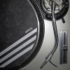
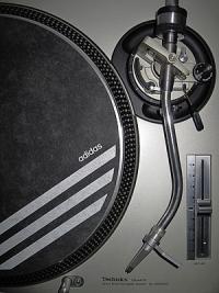
I'd like to share my very own idea of "the perfect portable": http://www.bilder-upload.eu/upload/641447-1506969503.jpg http://www.bilder-upload.eu/upload/bcc1ee-1506969607.jpg http://www.bilder-upload.eu/upload/74cf16-1506970125.jpg - Custom-made 3D-printed platter - Custom-made tonearm, adjustable counterweight - Modified Shure M44-7 cartridge - Phono-preamp (Av:Link STP-2) - Phono buttons (red, from top to bottom): Gain, Speed (relocated stock knob), Pitch, Start/Stop (modified Sanwa) - Custom made fader box (can house JDDX2RS or Innofader) - Raspberry Pi, AudioInjector soundcard, 5" touch display, plus PiDeck software => DVS inside - Button to switch between "phono" and "DVS" mode - USB port for MP3 files on a USB stick - Line-Out (Cinch & 3.5mm) - Relocated speaker position, high-quality 2" fullrange driver (Monacor SPX-21M) - Dedicated vented cabinet (~0.4 litres, tuned to 110 Hz), vent exits at the turntable's bottom to boost bass - 6W aplifier (Kemo M033N), power/volume knob - Headphone amplifier (M-Audio Bass Traveller) - Line-In - 5V 10Ah powerbank (Fontastic "Eta"), powers the DVS system and headphones amp, plus - 9V Step-Up power regulator to power the PT01 circuit boards It was all wired up and working before disassembling and preparing the parts for the "final build". So it's not 100% finished yet, i.e. cover plate, front/rear panels and faderbox cover plates are still missing,.. r
-
Suprême NTM (France) r
-
I am more than happy about having finished some ideas that have been bugging my mind since a while. I never liked that "tone" knob, so I decided to "put it to rest", and move the "speed selector" to that place. The less buttons, the better. All the board's parts are actually still in place, however the "tone" potentiometer's lever was chopped, and the "speed selector" was heavily chopped/modified. The rest is done through a few 3d-printed parts, including new buttons for volume/pitch. Same applies to the Start/Stop button "flush" install, which is a modified Sanwa button with 3d-printed FLAT cap (on the quality caps like Sanwa, You can take the cap off). I never liked the arcade buttons' round top. It's not all finished yet, just a dry-build. There's some more parts I made, the platter and the headshell, but I have elaborated on these more than enough in previous posts... I had intended to cover the whole thing with a decal in the end, but the more I actually worked on it, the more I liked the idea to keep it look "stock, with an unflashy twist" (even though I like that "rough" or "used" look of the Start/Stop, I believe it needs a final paint job). Little video, showing the functionality (and some really horrible scratch skills): https://www.youtube.com/watch?v=cKIp27xqcMg Longer version which also shows how You can install a platter within seconds (grab the ring from the top, not from the bottom): https://www.youtube.com/watch?v=gUvfgNJ0Avo Ah, so one controls voltage, and the other one currency? I finally understood why there are 2 switches visible in Your circuit diagramm (which I'm extremely thankful for). r
-
A few questions that arose from looking at the "audio" circuit board: - The speed selector is actually two 3-position buttons in one (parallel). Why is that? - The "tone" poetntiometer is stereo. But it seems that they only use one channel? - Same for the "volume" potentiometer? r
-
If it's just about "listening to music", why do You want to modify the tonearm? The tonearm is well made and ideally suited for hifi purposes. Switching to a better cartridge is like opening Pandora's box: You need the cartridge, a new tonearm, and a phono preamp. r
-
I found out by accident that You can also use Your 7" Serato instead of the test record... r edit: I have just seen that I finally found an ally in platter reinforcement... I haven't done a lot here since I built my own platter, but what I have learnt from my tests is that the reinforcement part must not put stress on the platter. Most platters are out-of-rund laterally, if You try to "cure" that with a reinforcement part, the platter will distort. Therefor it's advisable to leave slight gaps between platter and reinforcement part, and then fill the gaps with glue.
-
Been working on a couple of ideas... https://www.youtube.com/watch?v=62qH7_zEKYA r
-
No, that's the actual belt dimensions. (I had entered the PT01 dimensions into the calculation tool, sent him a screnshot of that, he proposed two belts, I bought and tried both, and what You see above is the belt that worked better) r
-
"Rubber band belt" or "flat belt". I still don't like the stock cartridge at all, but this idea had too much potential to remain unexplored (2.6 gramms on the needle, like stock) r Edit: I designed a little tonearm holder for the PT01. You can download the file here: https://www.youmagine.com/designs/numark-pt01-tonearm-holder