


Obi1jacobi
-
Posts
39 -
Joined
-
Last visited
Content Type
Profiles
Forums
Events
Posts posted by Obi1jacobi
-
-
Lookin dope, guys!
-
I'm going to try to reroute the the audio signal from the fader out and back to the speaker by using one of these
https://www.ebay.com/itm/262785379891
Would I need to upgrade the speaker?
-
That's badass! I'd like to make a 18650 pack or two but not sure how my high power vape batteries would work out being they are 35 amp batteries.. I have a few 10 amp batteries I've put in some other devices.. maybe I'll try those for gits and shiggles..
-
18650s are normally lipo too. Either will be fine.Would a lipo be a better battery type for use instead nimh rc packs or lithium 18650 cells?
So I made one 8.4v nimh pack and installed with deans connectors..seems to be running fine. Could I run 2 of these packs parallel at once to double the amperage but keep the same voltage?
https://instagram.com/p/BQgJ3nthdif
I also have a couple 18560 battery sleds that I'm going to put deans on to try 2x18650's since that'll put the pack at 8.4 as well..
-
Buying rechargeable d cells would totally be the logical thing to do;) but at moment I just gotta be careful how I spend money..my wife has been having problems with her health this past month and has taken leave from work.. And with a family of 5, it has been just as difficult to make extra money as it is to spending it. Hence my reusing and repurposing;p
-
Hmmmmm interesting..I've heard a lot about lipo batteries but have never used them for anything. I know you need special chargers for them or they can get super gnar gnar..I always try to make packs for devices that I want to have a longer lasting charge like a portable speaker or a vape mod or something... Would a lipo be a better battery type for use instead nimh rc packs or lithium 18650 cells?
-
These cells are usually 1.2v each, and I made a pack with 8 that puts me at 9.6v... strange thing is I pulled them off the charger to test the voltage output and its close to 11v... is that kinda like with lithium cells say they are 3.7v but when fully charged they're 4.2v?
-
The battery leads bypass the voltage regulator so you'll be fine.
With 9.6v or 12v? I just don't wanna cook my table..

-
Will a 9.6 battery pack (ni-mh rc car type)be too much voltage to use in the 01 connecting through the battery leads?
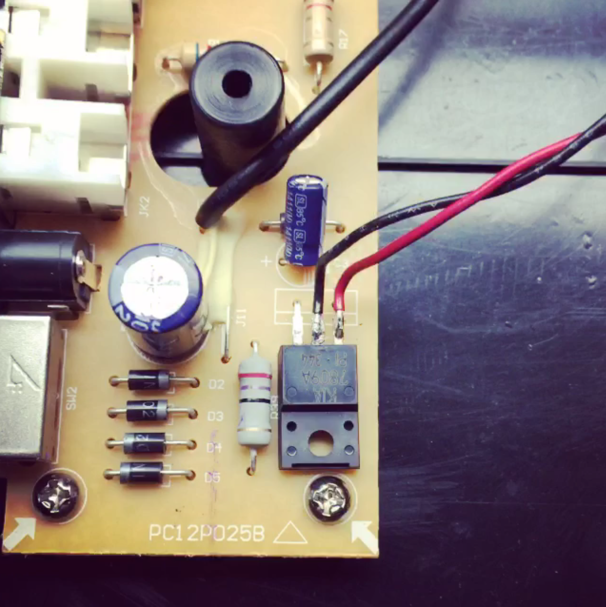
Thats fine, the voltage regulator can handle up to 18v.
http://www.beatshelter.com/wp-content/uploads/2016/04/pic1_PT01_regulator.png
Is it better to solder directly to this piece, to the actual battery lead? I also see some people using 12v batteries.. I can make either or battery pack...
-
Will a 9.6 battery pack (ni-mh rc car type)be too much voltage to use in the 01 connecting through the battery leads?
-
Does the fader pop worse when you wire it into c8/c18 than when you wire it externally?I don't understand why it's not working.... Does the earphone jack have a different signal from the main board ribbon? I also tried wiring into the c8&c18.. That actually gave sound but the fader kept popping, so I went back to the ribbon cable and still nothing.. Even tried rearranging the aux cords...
Rasteri thanx helping me see outside the box.. I've been racking my brain so hard on trying to get this the way I want it..more internally than externally..figured I'd just pull all my wires in the case itself..
https://instagram.com/p/BQOcQn3BQlA
It works but I think the record signal is trying to compete with the decoder signal... when I cut the fader on, the audio music seems to slightly drop.. not considerably, but enough to notice..
-
On another note.. Raiden fader reposted a pic of my boys on Instagram!

-
 4
4
-
-
Does the fader pop worse when you wire it into c8/c18 than when you wire it externally?I don't understand why it's not working.... Does the earphone jack have a different signal from the main board ribbon? I also tried wiring into the c8&c18.. That actually gave sound but the fader kept popping, so I went back to the ribbon cable and still nothing.. Even tried rearranging the aux cords...
You're right, I was to the point of exhaustiOn and felt crazy defeated earlier
I'm sorry,.. -
Yes you'll need resistors. You're mixing the signal so just connecting the two outputs together could damage them.I posted one potential solution earlier in the thread -Can anyone tell where i can solder the wires from the bluetooth decoder boards audio-out to(Numark PT01 USB(NOT the scratch version)?Cut the wires from TE8 and just solder it in between?Resistors or anything needed(its both line signal so i don't think so)?
Is this for wiring in a fader or auxiliary port?or both simultaneously?
-
I'd connect them after C8/C18 since the raiden will want an AC-coupled signal. So yeah splicing into the cable would be fine.There are 3 conductors: left, right, and ground.. 1 jack would feed audio to the fader from the Bluetooth module and the other two are for in/out on the fader. Im trying to narrow down the best place to connect them to the 01... do you think splicing into the big ribbon or connecting on the c8 & c18?
Yes.And in the end, could I plug in headphones in the headphone jack and still hear everything?
Not on the case no, either take ground from the power supply or somewhere on the main board.also would I just join the grounds from all the jacks and ground them to a grounding point on the case?
I don't understand why it's not working.... Does the earphone jack have a different signal from the main board ribbon? I also tried wiring into the c8&c18.. That actually gave sound but the fader kept popping, so I went back to the ribbon cable and still nothing.. Even tried rearranging the aux cords...
-
-
The jacks I made are faulty... just gonna cut some 3.5mm jacks in half
-
If it is, it hasn't been figured out yet..
-
thanx mayn! Gonna give it a go when I receive the rest of the pieces..
-
Oh yeah, thought I forgot something:p
-
1
-
-
Thought I'd start a new thread for this.
First step is to jot down a rough schematic for my PT01 so planning mods will be easier. Note that not all the components have the correct names yet.
Some things to note :
- This is for the PT01USB version, which has an extra connector (TE13) on the main board that sends the signal to the USB board, and the motor control circuit uses a different IC. The circuit looks broadly similar to the regular PT-01 however and the components have the same names.
- The top section of the schematic is the main audio/motor board, the bottom section is the power supply/IO board.
- Connector TE11 connects to TE12 via the black ribbon cable.
- The phono preamps are a common-emitter class A transistor design with no proper RIAA equalisation. This might actually be a good thing as most of us turn the bass down when cutting anyway.
- The L/R connectors on the black ribbon cable are actually AFTER the power amp. Wiring a fader in at this point probably isn't a great idea as they aren't really meant to handle that kind of power, but I guess if it works it works.
- A better place to put faders would probably be after the DC-blocking caps C8/C18, or perhaps after connector TE8 (the tone/volume knobs).
- For an AUX IN port, putting a couple of resistors in series with the AUX and connecting it to TE8 pins 1 and 3 (or 4 and 6 if you don't want it to be affected by the volume/tone knobs) would probably work.
Wussup Rasteri, was wondering if I could pick your brain in regaurds to your diagram..so if all else fails in finding fader ports (like on the scratch)on my 01, I want to install my raiden inside the case...I soldered these jacks to plug into the fader..
https://instagram.com/p/BP5eDZpB7t9/
There are 3 conductors: left, right, and ground.. 1 jack would feed audio to the fader from the Bluetooth module and the other two are for in/out on the fader. Im trying to narrow down the best place to connect them to the 01... do you think splicing into the big ribbon or connecting on the c8 & c18? And in the end, could I plug in headphones in the headphone jack and still hear everything? You know, like on those late nights when everybody in the house is sleeping but I have a crazy itch to scratch,lol..also would I just join the grounds from all the jacks and ground them to a grounding point on the case?
-
Nice work!
-
Hmmmmm innofader plus works for pt01 right out the box?
-
Weirdly, micro USB is more robust than mini USB.You can make a rechargable battery mod with a standard USB power bank and a boost converter to boost the 5v up to 9v, ebay search for "XL6009"I'm surprised how long cheap d-cells last.. my battery mod(when I get to it) will most definitely have the charging port fixed on the case of the 01..wheather it be mini USB or like the wall adapter plug. Sorry, I don't think I answered any of your questions but I think the going mah used is between 6800-10000..but don't quote me on that;p
I think I meant micro;) I knew one was better than the other...I used to build vape mods for friends and personal use so I have many 18650 batteries at the homestead.. also played a lot of airsoft as a teen/young adult so I have a bunch of rc battery packs as well...but I think it'd be less work to buy a 12v lipo pack with the charging in/out pigtail..but first I would like to install my fader.. last night I put a little credit card shim in my raiden vvt-mk1...now it's cut is razor sharp! I was going to mount it where the scratch switch is but once I found the case had the scratch switch hole, I'm going to leave that undisturbed until I find out more..
Numark PT-01 modding thread
in EQUIPMENT & AUDIO PRODUCTION
Posted
Maybe it's an iPhone thing....