

johnydest
-
Posts
9 -
Joined
-
Last visited
-
Days Won
1
Content Type
Profiles
Forums
Events
Posts posted by johnydest
-
-
yeah thats the funny part, there were not empty metal lids inside the mixer
-
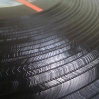
yeah not only poor quality but if you see at the picture 2 of them have no enclosure at all... I am suprised they worked in the first place
-
So my Mixars Cut had a problem. One of the XLR outputs stopped working. The RCA outputs where both working, so I opened it to see if there is something wrong with the XLR connections.
Opening the mixer I noticed that most of the space inside was empty. They could make the mixer smaller, all the weight comes from the thick metal casing.

I was looking for anything unusual at the XLR area. I am not an expert but what I found was something really noticeable.
Two of the capacitor where ''naked''. Thats the first time I see something like that. I dont know if this is normal.
I replaced all 4 capacitors at this spot and the mixer seems to work fine for now.
That was very disapointing. I know that this is a budget mixer and you get what you pay for. I know some things come out of the factorie wrong but this is surely not a ''Mini tank'' as advertised.

-
Thank you very much Rasteri!
So what is left to find out is which of the pink/red dots is the Left and which is the Right channel. I suppose there will be a problem if they are connected wrong. -
I found some photos I took of the mod the last time I did it -
http://www.digitalvertigo.co.uk/forum/index.php?showtopic=37018&p=395602
You might just be able to reverse engineer it from that
I am trying to reverse engineer the mod.
I have located the pins that the cables are soldered but I dont know how they are connected to the switch.
In this picture I mark the pins from both sides of the boards.
Would this help you tell how are the cables coneected to the switch?
-
Thanks rasteri,
so if you want to use the fader on other VCA mixer the only requirement is that this mixer has the same Voltage at ''V+'' as the stanton?
-
Hi
In my opinion focus fader is the best fader out there. It is simple and does what I need, it cuts without any unnecessary tension-fade calibrations and other expensive stuff.
I try to find out how it works
I am not so good at circuits and i cant read a circuit diagram so i opened my fader and tried to understand and I need your help to tell me if i got it right.So here is the focus fader
This is a drawing I made
So the powers comes in at V+ and it brakes to 2 ''paths''. The one powers the 2 opto interrupters and then goes to Ground. The other sends power to VC1 and VC2 which are the channels of the mixer, so when there is power sent the sound is ON but when the opto interrupter is closed there is no power sent so the sound is OFF. Both channels are connected to ground with resistor.
Did i get it right? Is this how it works?
-
 5
5
-
Repairing Mixars Cut
in EQUIPMENT & AUDIO PRODUCTION
Posted
I knew caps can leak but I didn't know caps can explode, wow!